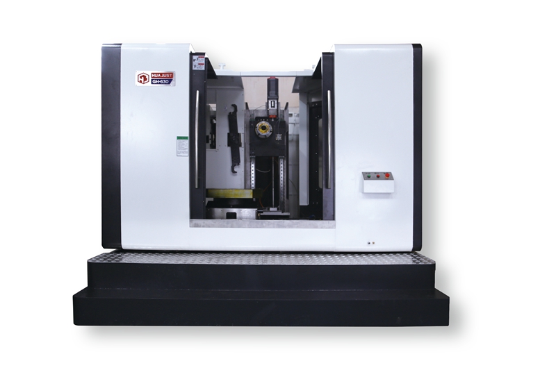
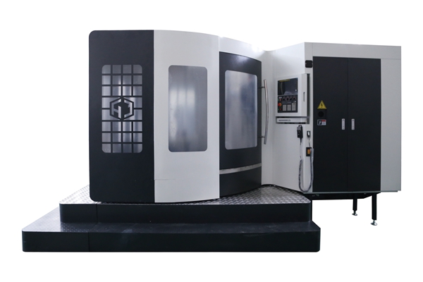
Liner rail of X/Y/Z axis, composite and integrated horizontal machining center(High performance-price ratio


Introduction of product advantages
Adopt the international popular inverted T-shaped moving-column type and integral lathe bed structure. Reasonable ribs arrangement optimizes chips disposal structure, improves guide rail lubrication recovery system, and enhances the integral rigidity and appearance quality of castings.
The installation and support components (motor base and bearing base) of the three-axis feed system of the machine tool are completely guaranteed by mechanical processing, which greatly improves the assembly efficiency and quality, and enhances the accuracy consistency. (In the past, the adjusting pad under the joint surface of the motor base and the bearing base of the machine tool was manually adjusted, resulting in low assembly efficiency. Due to the uneven ability of assembly workers, the assembly quality is unstable, thus leading to the instability of machine tool precision.)
Introduction of lathe bed structure
Arrange a screw chip conveyer interface in the machine and install a cutting and flushing device to automatically discharge chips in time, thus avoiding the thermal influence of chips on the machine tool and ensuring the high accuracy of machine tool processing.
According to the requirements of the automobile manufacture industry, the form of the machine tool table is changed from T-slot to screwed hole, which provides convenience for tools and fixtures, avoids the situation that it is difficult to ensure the secondary processing accuracy of the center T-slot, and greatly improves the rigidity and stability of the table. (The T-slot greatly reduces the rigidity of the machine tool table, and the table is greatly deformed under tension.)
Technical Parameters
| Basic specification: | unit | GH-500 | GH-630 | GH-800 | GH-1290 |
| Stroke | |||||
| Strokes of Axes X, Y and Z | mm | 740×680×650 | 1050×750×900 | 1300×1000×1000 | 1200×900×700 |
| Nose of the Spindle to the Table Surface | mm | 120-800 | 120-870 | 120-1120 | 70-970 |
| Center of the Spindle to the Shield Surface of Axis Z | mm | 130-780 | 130-1030 | 200-1200 | 150-850 |
| Maximum Load of the Table | |||||
| Table Size | mm | 500×600 | 630×700 | 800×800 | 1300×700 |
| Maximum Load of the Table | kg | 600 | 950 | 1500 | 1000 |
| Size of T-Shaped Slot (Width * Number of Slots * Interval) | mm | 24XM16Threaded hole | 24XM16Threaded hole | 24XM16Threaded hole | 18×5×122 |
| Spindle | |||||
| Revolving Speed of Spindle | rpm | 6000 | 6000 | 6000 | 6000 |
| Horsepower of Spindle Motor | kw | 15/18.5 | 15/18.5 | 18.5/22 | 15/18.5 |
| Taper of Spindle | BT-50 | BT-50 | BT-50 | BT-50 | |
| Diameter of Spindle | mm | 155/190 | 155/190 | 190 | 155/190 |
| Feed Rate | |||||
| Maximum feed rates of Axes X, Y and Z | m/min | 20×20×20 | 20×20×20 | 20×20×20 | 20×20×20 |
| Accuracy | |||||
| Repeated Accuracy | mm | ±0.003 | ±0.003 | ±0.003 | ±0.003 |
| Positioning Accuracy | mm | ±0.005 | ±0.005 | ±0.005 | ±0.005 |
| Automatic tool changer | |||||
| Form of Tool Changer | Knife arm | Knife arm | Knife arm | Knife arm | |
| Capacity of the Tool Magazine | support | 24 | 24 | 24 | 24 |
| Maximum Tool Diameter | mm | 105/200 | 105/200 | 105/200 | 105/200 |
| Maximum Tool Length | mm | 350 | 350 | 350 | 350 |
| Maximum Tool Weight | kg | 15 | 15 | 15 | 15 |
| Tool changing time (T-T) | sec | 6 | 6 | 6 | 7.5 |
| Power Source | |||||
| Pressure of air machine | kgf/cm2 | 7 | 7 | 7 | 7 |
| Power demand | KVA | 35 | 35 | 40 | 35 |
| Size and weight of the machine | |||||
| Net weight | T | 11 | 13 | 17 | 13 |
| Overall size (length * width*height) | m | 2.8×4.6×2.9 | 3.5X5X2.9 | 4.3X6.1X4 | 3.6×3.25×2.95 |

